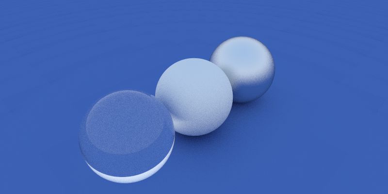
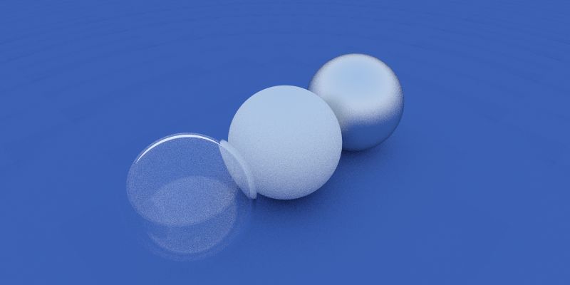
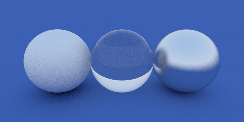
Chapter 9 study note. Breakdown topics about basic optic physics (refractive index, Snell’s Law, total reflection, Fresnel coefficients, Schlick’s approximation) and vector maths for calculating refraction ray.
Dielectric Transparent Material
Dielectric material can reflect light and at the same time let the light pass through - refract.
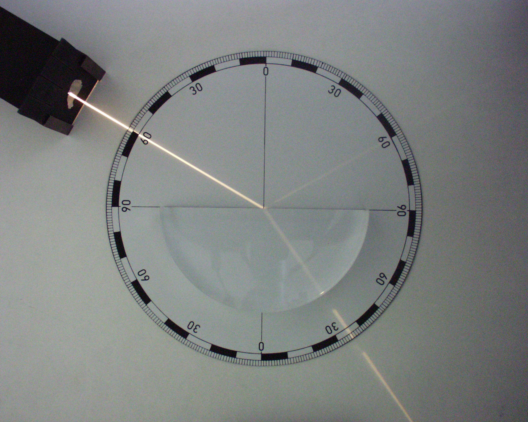
Refraction of Dielectric Material
Refractive Index
Refractive index describes how light propagates through that medium. It is defined as
\[n={\frac {c}{v}}\]where $c$ is the speed of light in vacuum and $v$ is the speed of light in the medium.
Refractive index $n$ in some common materials:
- Vacuum 1
- Air 1.000293
- Water 1.333
- Ice 1.31
- Window glass 1.52
- Diamond 2.42
The refractive index determines how much the path of light is bent, or refracted, when entering a material. This can be described by Snell’s law of refraction.
Snell’s Law of Refraction
\[{\frac {\sin \theta _{2}}{\sin \theta _{1}}}={\frac {v_{2}}{v_{1}}}={\frac {n_{1}}{n_{2}}}\]Snell’s law states that the ratio of the sines of the angles of incidence and refraction is equivalent to the ratio of phase velocities in the two media, or equivalent to the reciprocal of the ratio of the indices of refraction:
with each $\theta$ as the angle measured from the normal of the boundary, $v$ as the velocity of light in the respective medium, $n$ as the refractive index (which is unitless) of the respective medium.
So if here we only consider rendering object with dielectric material (with a refractive index ${n_{dielectric}}$, defined as ref_idx in code) in a vacuum environment, since the $n$ of vacuum is 1, we get
when ray shoots into object,
and when ray shoot through object back into vacuum,
\[\frac {n_{1}}{n_{2}} = {n_{dielectric}}\]Define the dielectric material class:
class dielectric : public material {
public:
    dielectric(float ri) : ref_idx(ri) {}

    virtual bool scatter(const ray& r_in,
                 const hit_record& rec,
                 vec3& attenuation,
                 ray& scattered) const;

    float ref_idx;
};
Total Internal Reflection
When light travels from a medium with a higher refractive index to one with a lower refractive index, $\theta_{2}$ is larger than $\theta_{1}$. When $\theta_{2}$ is reaching 90 degree and $\theta_{1}$ keeps getting bigger, light could be completely reflected by the boundary.
The largest possible angle of incidence which still results in a refracted ray is called the critical angle.
Refraction Vector
Calculation
With all the knowledge above, we can calculate refraction vector. First we can model the vectors relationship within a unit circle to simplify the vector calculation.
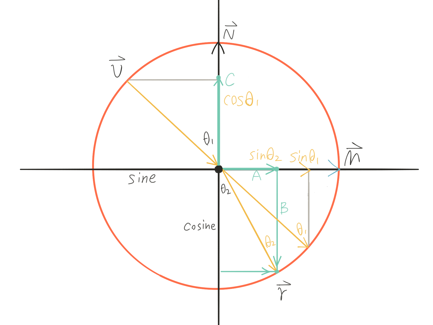
Note that when doing vector calculation, we have to be aware of both direction and the length/magnitude of the vectors.
\[\vec A = sin\theta_{2} \cdot \vec M\] \[\vec B = cos\theta_{2} \cdot -\vec N\] \[\vec M = Normalize(\vec C + \vec v) = (\vec C + \vec v)/sin\theta_{1}\] \[\vec C = cos\theta_{1} \cdot \vec N\]Expand and rearrange the equation we get:
\[\vec r = \frac {n_{1}}{n_{2}} \cdot (\vec v + cos\theta_{1} \cdot \vec N) - cos\theta_{2} \cdot \vec N\]$\vec r = \frac {n_{1}}{n_{2}} \cdot (\vec v - cos\theta_{1} \cdot \vec N) - cos\theta_{2} \cdot \vec N$ when we make $\vec v$ point away from the hit point.
After normalizing incidence ray direction $\vec v$, we can calculate $cos\theta_{1}$ by \(dot(\vec v, \vec n) = \vert \vec v\vert \vert \vec n\vert cos\theta_{1} = cos\theta_{1}.\)
Since
\[sin\theta_{2} = \frac {n_{1}}{n_{2}} \cdot sin\theta_{1},\]we get
\[cos^2\theta_{2} = 1 - sin^2\theta_{2} = 1 - \frac {n_{1}^2}{n_{2}^2} \cdot sin^2\theta_{1} = 1 - \frac {n_{1}^2}{n_{2}^2} \cdot (1 - cos^2\theta_{1}) = 1 - \frac {n_{1}^2}{n_{2}^2} \cdot (1 - dot(\vec v, \vec n))\]And the equation becomes:
\[\vec r = \frac {n_{1}}{n_{2}} \cdot (\vec v - dot(\vec v, \vec n) \cdot \vec N) - \sqrt{1 - \frac {n_{1}^2}{n_{2}^2} \cdot (1 - dot(\vec v, \vec n))} \cdot \vec N\]So $cos^2\theta_{2} = 1 - \frac {n_{1}^2}{n_{2}^2} \cdot (1 - dot(\vec v, \vec n))$ is the discriminat of the equation:
- when $discriminat > 0$, we have refracted ray $\vec r$;
- when $discriminat < 0$, we will encounter total reflection and have no refraction ray - ray will be reflected back into the object.
- note that $discriminat = 0$ is the boundary of total reflection when refracted ray is perpendicular to the surface normal - no reflection nor refraction.
Code
Define $\frac {n_{1}}{n_{2}}$ as ni_over_nt, v is incidence ray direction, n is surface normal, refracted is the refracted ray direction.
bool refract(const vec3& v, const vec3& n, float ni_over_nt, vec3& refracted) {
    vec3 uv = unit_vector(v);
    float dt = dot(uv, n);
    float discriminat = 1.0 - ni_over_nt * ni_over_nt * (1-dt*dt);
    if(discriminat > 0){
        refracted = ni_over_nt * (uv-n*dt) - n*sqrt(discriminat);
        return true;
    }
    else
        return false; // no refracted ray
}
Reflection of Dielectric Material
Fresnel Equations
When light strikes the interface of a medium of a given refractive index, n1 and a second medium with refractive index, n2, both reflection and refraction of the light may occur.

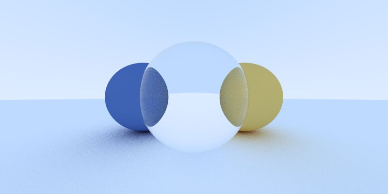
Notice there are both light reflection and refraction observable on the glass sphere.

For example in Escher’s this painting, we can see the water is more transparent close by (bigger viewing angle, more light transmission and refraction) and more reflective far away (smaller viewing angle, more light reflection).
The Fresnel equations (or Fresnel coefficients) describe the ratio of reflection and transmission of light.
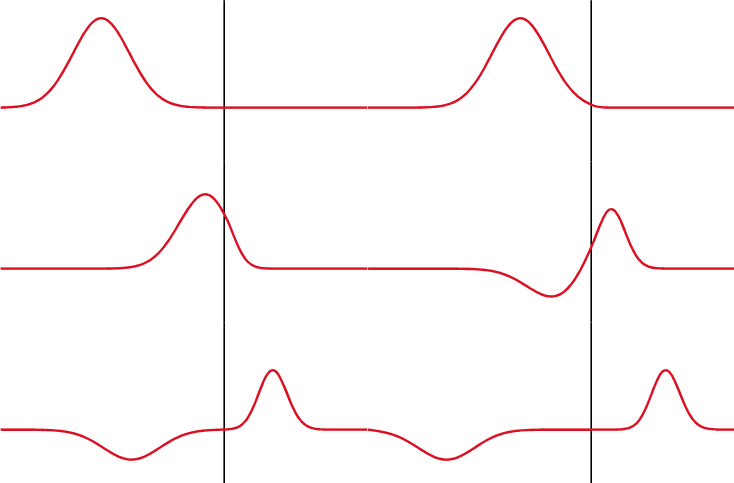
A wave experiences partial transmittance and partial reflectance when the medium through which it travels suddenly changes. The reflection coefficient determines the ratio of the reflected wave amplitude to the incident wave amplitude.
However for low-precision applications involving unpolarized light, such as computer graphics, rather than rigorously computing the effective reflection coefficient for each angle, Schlick’s approximation is often used.
Schlick’s Approximation
In 3D computer graphics, Schlick’s approximation is a formula for approximating the contribution of the Fresnel factor.
According to Schlick’s model, the specular reflection coefficient $R(\theta)$ can be approximated by:
\[R(\theta_{1})=R_{0}+(1-R_{0})(1-\cos \theta_{1} )^{5}\] \[R_{0}=\left({\frac {n_{1}-n_{2}}{n_{1}+n_{2}}}\right)^{2}\]where
- $\theta_{1}$ is the incident angle (the angle between the direction from which the incident light is coming and the normal of the interface between the two media).
- $n_{1},\,n_{2}$ are the refractive indices of the two media at the interface and
- $R_{0}$ is the reflection coefficient for light incoming parallel to the normal (i.e., the value of the Fresnel term when $\theta_{1} =0$ or minimal reflection).
In computer graphics, one of the interfaces is usually air ($n_{air} = 1.000293$), meaning that $n_{1}$ can be approximated as 1.
Recall that ref_idx is ${n_{dielectric}}$ and when ray shoots into object,
float schlick(float cosine, float ref_idx) {
    float r0 = (1 - ref_idx) / (1 + ref_idx); // ref_idx = n2/n1
    r0 = r0 * r0;
    return r0 + (1 - r0) * pow((1 - cosine), 5);
}
Put All Together
Note that we still use function scatter() to pack up all the work.
bool scatter(const ray& r_in,
             const hit_record& rec,
             vec3& attenuation,
             ray& scattered
             ) const {

    attenuation = vec3(1.0,1.0,1.0);

    vec3 outward_normal;
    vec3 reflected = reflect(r_in.direction(), rec.normal);
    vec3 refracted;

    float ni_over_nt;
    float reflect_prob;
    float cosine;

    // Dealing with Ray Enter/Exit Object
    // Dealing with Ray Reflection/Refraction (Fresnel)

    return true;
}
Dealing with Ray Enter/Exit Object
// when ray shoot through object back into vacuum,
// ni_over_nt = ref_idx, surface normal has to be inverted.
if (dot(r_in.direction(), rec.normal) > 0){
    outward_normal = -rec.normal;
    ni_over_nt = ref_idx;
    cosine = dot(unit_vector(r_in.direction()), rec.normal);
}
// when ray shoots into object,
// ni_over_nt = 1 / ref_idx.
else{
    outward_normal = rec.normal;
    ni_over_nt = 1.0 / ref_idx;
    cosine = -dot(unit_vector(r_in.direction()), rec.normal);
}
Dealing with Ray Reflection/Refraction (Fresnel)
If the traced ray produce a refraction ray (refract() returns true, and record refracted ray direction in vec3& refracted), we are going to calculate the reflective coefficient reflect_prob. If not, this means the ray encounters total reflection and the reflective coefficient should be 1.
// refracted ray exists
if(refract(r_in.direction(), outward_normal, ni_over_nt, refracted)){
    reflect_prob = schlick(cosine, ref_idx);
}
// refracted ray does not exist
else{
    // total reflection
    reflect_prob = 1.0;
}

Both reflection and refraction of the light occur for dielectric material, but we can only pick 1 scattered ray for next iteration of ray tracing. Since we are shooting multiple rays per pixel (multi-sampling) and average the traced color as final pixel color, we can use the same idea to get the averaged result through both reflectiona and refraction.
Now we generate a random number between 0.0 and 1.0. If it’s smaller than reflective coefficient, the scattered ray is recorded as reflected; If it’s bigger than reflective coefficient, the scattered ray is recorded as refracted.
Note that when total reflection happens, with reflective coefficient = 1, the random number will be always smaller than it and we only record the reflected ray.
Hence we get the code here:
if(drand48() < reflect_prob) {
    scattered = ray(rec.p, reflected);
}
else {
    scattered = ray(rec.p, refracted);
}
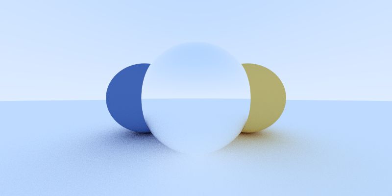
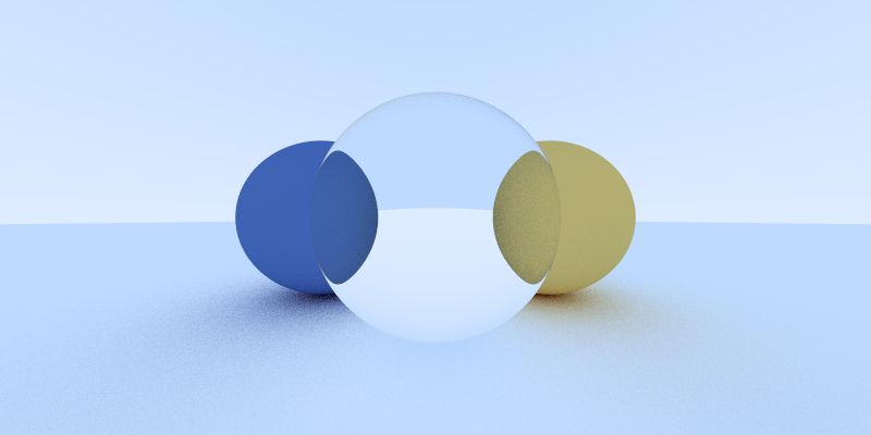
Additional Tricks
I edit the dielectric material class to make the transparent material have color as well.
// class definition
class dielectric : public material {
public:
    dielectric(const vec3& a, float ri) : albedo(a), ref_idx(ri) {}

    bool scatter(const ray& r_in,
                const hit_record& rec,
                vec3& attenuation,
                ray& scattered
                ) const {
                    attenuation = albedo;
                    // ...
                }

    vec3 albedo;
    // ...
};
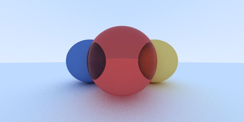
Also if we add an extra sphere with negative (and slightly smaller) radius inside the glass sphere, we will achieve a hollow glass look.
